
Open ten bracket drawings from ten different design teams and you’ll find GD&T callouts that look remarkably similar — not because the parts have similar functional requirements, but because most CAD templates ship with a default tolerancing scheme and most engineers, understandably busy, leave it in place. That habit is expensive in a way that rarely gets traced back to its source: every GD&T callout tighter than the part actually needs is a real cost at the fabricator, in inspection time, in process control, and sometimes in the process itself.
Why GD&T drives cost the way it does
A tolerance isn’t just a number on a drawing — it’s an instruction to control a process tightly enough, and inspect it thoroughly enough, to guarantee that number. Loosening a callout from a tight class to a standard one doesn’t just relax a spec; it can move a feature from requiring a coordinate-measuring-machine (CMM) inspection to a caliper check, or from a slow, careful machining pass to a standard one. Multiply that across every dimension on a bracket with a dozen features and the cumulative effect on cycle time and inspection load is where the price difference actually comes from — not from the material or the basic process.
The callouts that usually matter — and the ones that usually don’t
Flatness and parallelism on a mounting face matter when the bracket seats against another surface and a gap changes an electrical, thermal or sealing outcome — a heat-sink interface or a gasketed joint, for instance. On a face that’s just a mounting surface for fasteners with reasonable clamping force, standard machining flatness is almost always enough, and a tight flatness callout there is paying for nothing.
Position tolerance on hole patterns matters when the bracket must mate to a fixed pattern on another part with no adjustment available — a blind-hole pattern into a housing, say. Where the mating hardware has any slot, slip, or fastener clearance to absorb variation, position tolerance can usually be relaxed a class or two without any functional risk, and this is one of the most common over-specifications on first-pass drawings.
Profile tolerance on a complex or cast surface matters when the surface itself does something — seals against another part, forms an aerodynamic or optical surface, or mates to a matched counterpart. On a non-functional cosmetic surface, profile tolerance should track the process capability of the chosen method (die casting, CNC, sheet forming) rather than an arbitrarily tight number that forces secondary finishing just to pass inspection.
Perpendicularity and angularity matter wherever a feature has to align with another axis for a mechanism to move correctly — a shaft bore relative to a mounting face, for example. Where there’s no moving interface, these callouts are frequently inherited from a template and add inspection cost without protecting any actual function.
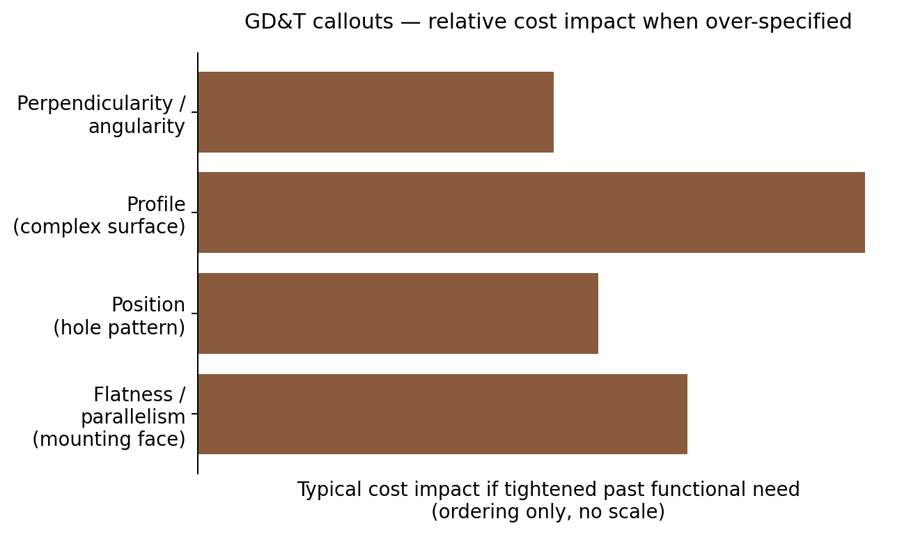
Callout impact at a glance
| GD&T callout | When it’s genuinely load-bearing (functional) | When it’s usually over-specification | Typical cost impact if tightened past need |
|---|---|---|---|
| Flatness / parallelism (mounting face) | Thermal, sealing or electrical interface depends on contact | Fastener-clamped mounting face with no interface function | Moderate–high (may force grinding/lapping) |
| Position (hole pattern) | Blind mating pattern, zero mechanical clearance available | Slotted or clearance-fastened joints | Moderate (CMM inspection, tighter fixturing) |
| Profile (complex/cast surface) | Sealing surface, mating counterpart, aerodynamic/optical function | Cosmetic or non-mating surface | High (may force secondary machining of a cast/formed part) |
| Perpendicularity / angularity | Alignment for a moving mechanism or bore | Static, non-interfacing feature | Moderate (fixturing and inspection time) |
Treat this table as a starting conversation, not a substitute for engineering judgement on your specific bracket — the right callout always follows the actual function, in either direction.
Over-specification patterns worth watching for
The most common pattern is a tolerance carried over from a previous, unrelated design where it was genuinely needed, then copied into a new drawing where the geometry looks similar but the function doesn’t match. The second is applying a single tight GD&T scheme uniformly across every feature on the drawing “for consistency,” rather than reserving tight callouts for the handful of features that actually need them and leaving everything else at standard process capability. The third is specifying true position or profile tolerances without first checking what the manufacturing process (die casting, CNC, sheet metal) can hold as standard — asking for a tolerance the process comfortably exceeds by default costs nothing; asking for one it can only meet with extra steps costs real money, and it should be a deliberate choice, not an accident of the template.
A practical simplification approach
Go through the drawing feature by feature and ask, for each toleranced dimension: what actually breaks if this is looser? If the honest answer is “nothing, mechanically or functionally,” the tolerance is a candidate for relaxing to the process’s standard capability. If the answer is a real functional consequence — a seal fails, an assembly won’t go together, a mechanism binds — that’s exactly the feature that should carry the tight callout, and it’s worth calling it out explicitly as functionally critical on the drawing so it doesn’t get value-engineered away later by someone who doesn’t know why it’s there. This pass typically finds that a bracket needs tight control on two or three features and standard control everywhere else — which is a very different, and usually much cheaper, drawing than one with uniform tight tolerancing throughout.
What to put on the RFQ
Mark functionally critical features explicitly, separate from the general tolerance block, so the fabricator knows where inspection effort actually needs to go. State the mating condition for any interface tolerance (bolted with clearance, blind-mated, sealed, sliding) so CNC machining or die casting can be matched to what the feature actually requires. And if the bracket’s process choice itself is still open, our earlier guide on matching the metal process to your part and the companion piece on surface finishing and how it interacts with tolerances are worth reading alongside this one, since GD&T, process choice and finish all pull on the same drawing.
Where PA fits
Through its network of specialist manufacturing partners, PA International works across CNC machining, die casting and metal fabrication, applying process capability data at quote stage so a drawing’s tolerancing gets checked against what the chosen process actually holds — before tooling, not after a rejected first article.
If you have a bracket drawing about to go out for quote and you’re not sure which callouts are protecting function and which are just template defaults, send it over — we’re happy to look it over before the metal moves. Get in touch to review a drawing.